
2015-05-05 »
All Natural MIMO
In response to my last post about beamforming, some people wrote to say that MIMO (multi-input multi-output signal processing) is not so complicated and is easy to explain: in fact, your eyes do it.
Now, that's a fun example. It's not exactly how MIMO works in wifi, but it's a good way to start to understand. Let's look at it in more detail.
Imagine you place an array of LEDs some distance away from your eyes (say, 50 meters away)
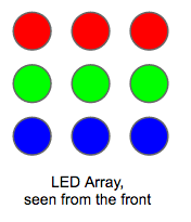
Assuming there's no interference between the LEDs - which we'll get to in a moment - they can all be considered separate signals. So if they change colour or brightness or toggle on and off, they can each send a message independently of the others. That's common sense, right? And the maximum rate at which each one can send messages is defined by the Shannon limit, based on the colour spectrum your LEDs are able to produce (the "bandwidth" of the signal) and the ambient light (the "noise").
And so, trivially, this is an example of "cheating" the Shannon limit: by using several lights, you can send more data per unit time, using the same frequency spectrum, than the Shannon limit says you can.
Lenses
Okay, so why can your eyes so easily bypass the limit, while your wifi can't?
The answer is interference between the individual signals. Above, we assumed that there is no interference between the LEDs. That's (mostly) true in this case, because your eyes act like an array of highly directional antennas. Assuming your eye's lens works correctly, every point on the grid you're looking at will end up projected onto a different sensor on your retina. Like this:
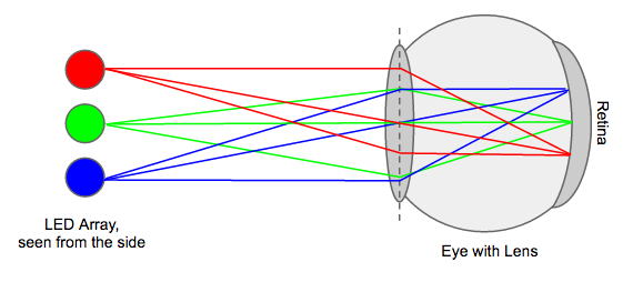
Notice how each light emits rays in every direction, but for the rays that actually reach your eye, all the rays from any one light always end up focused on the same point on your retina. Magic!
The maximum number of lights is limited by the quality of your eye's lens and retina, atmospheric interference, etc. That's why a space telescope - with no atmospheric interference and a really great lens - can pick up such great high-resolution images at huge distances. Each "pixel" in the image can vary its signal with the Shannon limit.
Lenses are pretty cool. Just to put that into perspective, here's what you'd get without a lens:
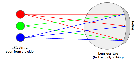
Notice how every point on the retina is receiving a signal from every light in the array; the result is a meaningless blur. If you want an example of this in real life, imagine setting up a white projector screen 50 meters away from your LED array. What shows up on the screen? Nothing much; just a bunch of blurred colour. As you move the LED array closer and closer to the projector screen, the picture gets clearer and clearer, but is always a bit blurred unless you have a lens.
Most of what you need to know to understand lenses, you probably learned in high school, but since I forgot most of what I learned in high school, I had to look it up. A good reference site seems to be physicsclassroom.com, which has all the lens math I vaguely remembered from school. It also has an Interactive Lenses and Mirrors toy, from which I clipped this helpful example:
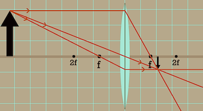
In this diagram, the big black arrow on the left is the object you're looking at, and the upside-down black arrow on the right is the image projected onto your retina.
'f' is the focal distance of your eye's lens, which is quite short, since the image is projected on your retina, which is less than 2f away. Since the focal distance is so short, almost any object you look at will be much more than 2f away, as shown in this picture. In that case, mathematically it always turns out that the image will be projected somewhere between distance f and 2f beyond the lens.
Your eye adjusts the lens (and thus the focal distance f) by contracting or releasing its muscles until the image is focused properly on the retina.
You can generally find the point where any given part of the image will appear by drawing three lines from the input (the top of the left-hand arrow in this case): a line straight through the center of the lens, a line directly horizontal, which bends at the lens to pass through point f on the right, and a line passing through f on the left, which bends at the lens to become horizontal. The point where all three lines intersect is the location of the image.
And that's MIMO, the way evolution intended. Sadly, it's not how MIMO works with wifi, because unlike your eyes, the wifi antennas in your laptop or phone are not very directional, not adjustable, and don't use lenses at all. In fact, what wifi receivers see is more like the blurred mess on the projector screen that we talked about earlier. We then unblur the mess using the amazing power of math. Next time!
2015-05-07 »
Rule #1 of product support: if the customer is hurting because of something you did, "working as intended, and it definitely hasn't happened to anybody else, we promise" doesn't make them feel any better.
2015-05-08 »
Dear everyone making tools based on debian/ubuntu:
If your upgrade script runs apt-get more than exactly once, you have completely missed the point of apt and dpkg.
2015-05-10 »
Finally, some actionable advice:
https://hbr.org/2014/10/hacking-techs-diversity-problem
2015-05-11 »
I'm pretty sure this must be the same process that was used to "design" the Makefile syntax.
2015-05-14 »
"To measure end-to-end delay you need to point the video camera at a stopwatch (digital or analog, doesn't matter) and then take a photograph that captures both the stopwatch and the far-end on-screen reproduction of the stopwatch. You won't be able to judge delay by eye, unless it gets really big and annoying."
– Mitchell Trott
That's an interesting low-tech solution to the surprisingly difficult problem of measuring video delay.
2015-05-15 »
Rule of thumb: If there's a weekly meeting for the project you work on, and you need to miss it this week, and then nobody else knows what to do in the meeting, then you're the tech lead. Doesn't really matter what it says in the org chart. :)
2015-05-21 »
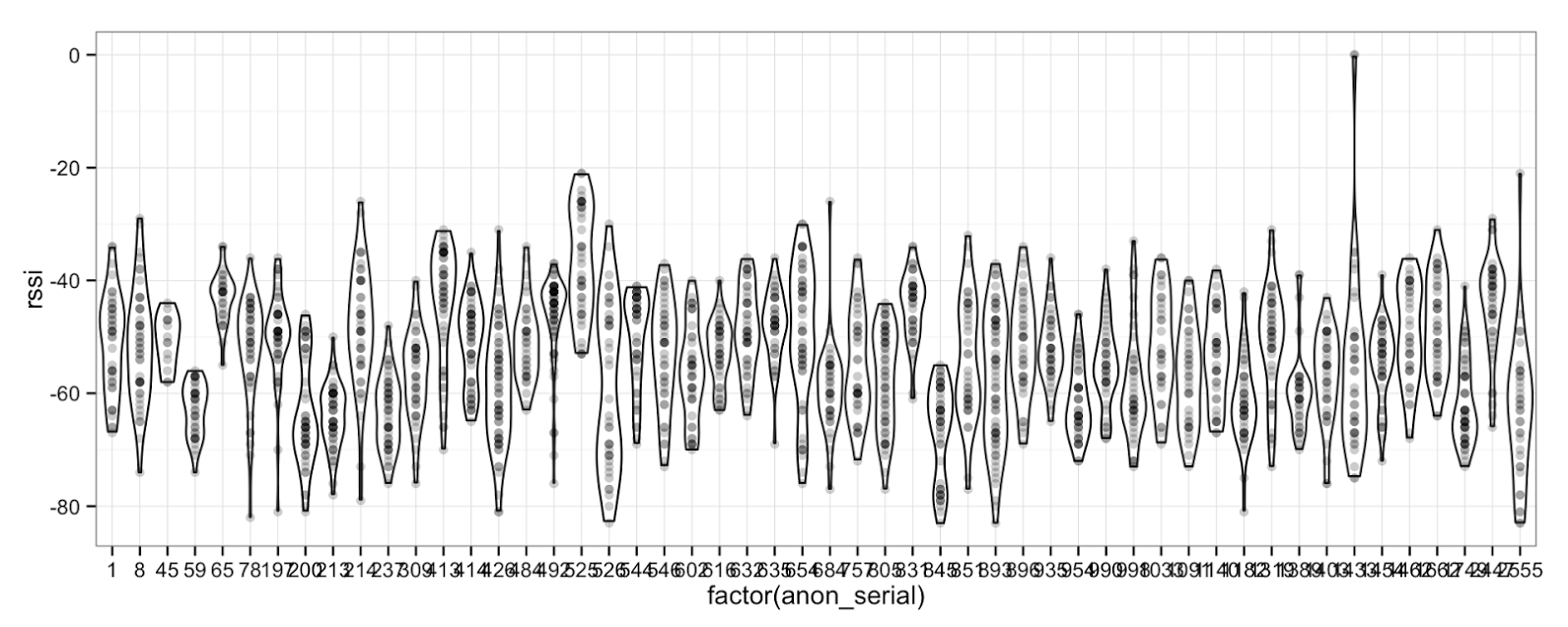
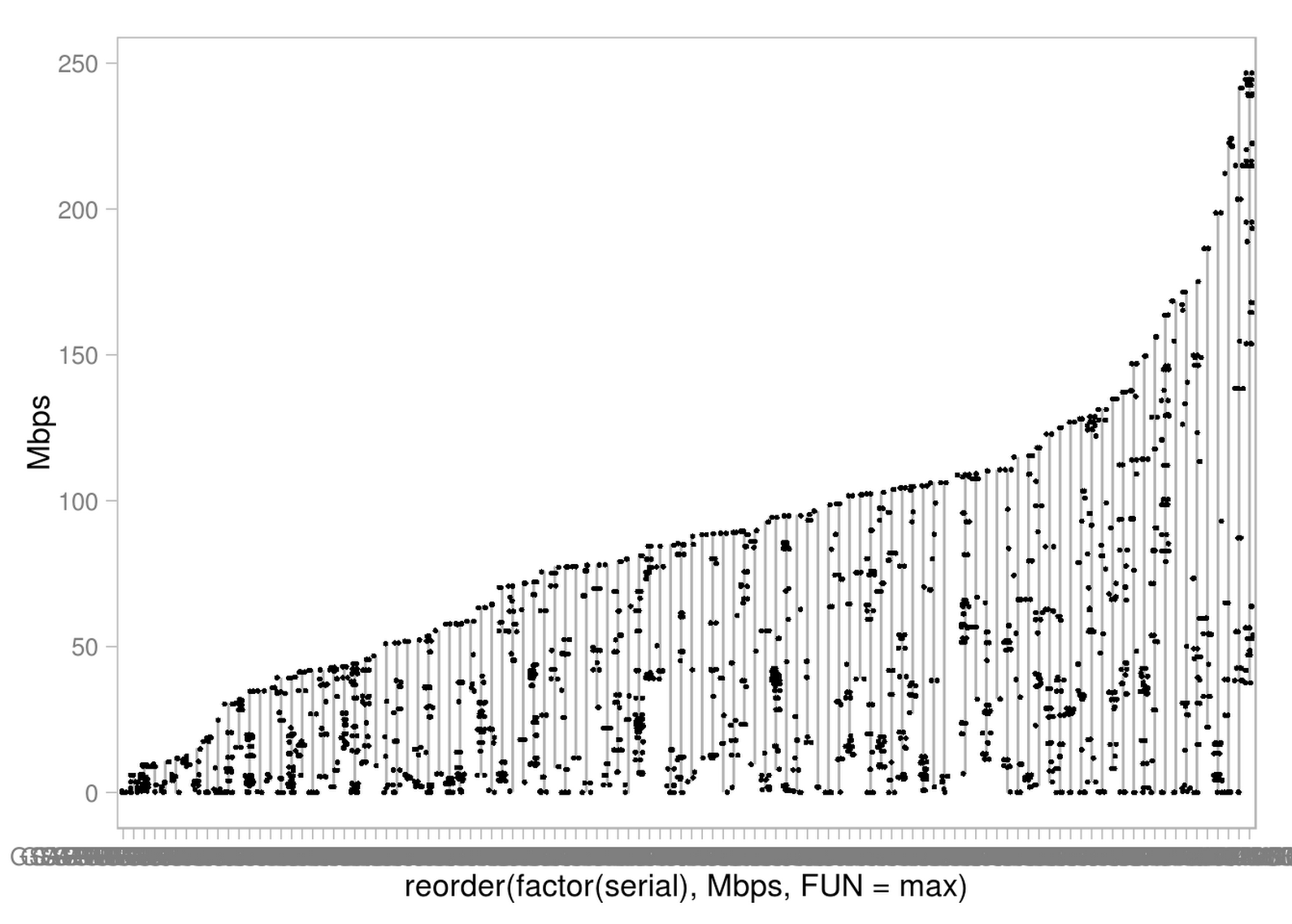
They say there are lies, damn lies, and statistics. Finally the wifi gattaca test has all three!
(Horizontal axis is individual wifi routers, sorted from "least best" to "most best" in terms of best-datarate-ever-observed. The dots along each vertical line are individual transfer rate samples from stations attached to that router. Eventually we should split the data per station to see if the variability is inside a given station or just across stations, but... not today.)
2015-05-22 »
Public service announcement: the experiment framework is not a turing machine. Do not attempt to use it as a turing machine, even if you find out it's possible to do so. Also, CLs implementing strong AI in the experiment framework will be rejected.
2015-05-24 »
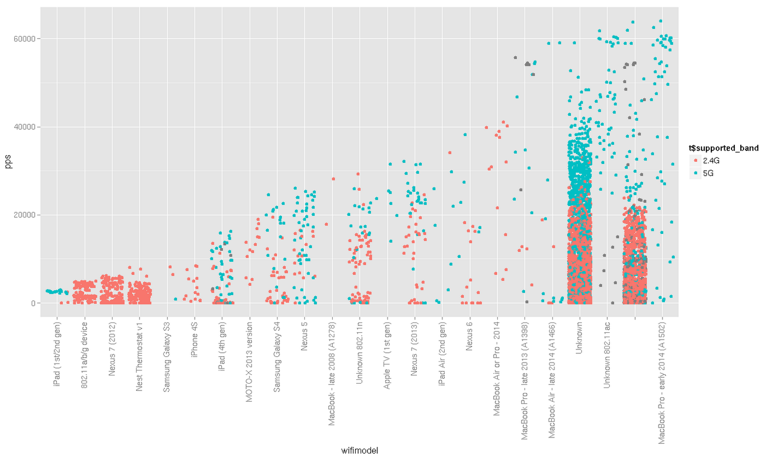
Shocking news everyone! 5GHz-capable wifi devices are faster than 2.4GHz-only wifi devices, even when you plot it by device model.
(I don't know why some specific device models seem to show a mix of 2.4GHz and 5GHz capable features. I think we might be mis-detecting it in some cases. 2.4GHz-only devices reliably show up only as 2.4GHz though.)
The most common device type is "unknown." Oh well.
Why would you follow me on twitter? Use RSS.